Wood has evolved to Metal!

A significant portion of our parts were waterjetted from sheet aluminium today! I’ve never used a waterjet before so that was utterly awesome.

Charles and Justin, awesome dudes who helped us waterjet it and brought the metal sheets to the archi lab and back to IDC.

Charles and Justin, awesome dudes who helped us waterjet it and brought the metal sheets to the archi lab and back to IDC.

The sign is very literal.

The sign is very literal.

Andrew being awesome

Andrew being awesome

Samuel being retarded

Samuel being retarded

Sheet metal marked with our kart number.

Sheet metal marked with our kart number.

OMAX is apparently the brand of the waterjet we have in SUTD as well. But ours is bigger. Bwahaha.

OMAX is apparently the brand of the waterjet we have in SUTD as well. But ours is bigger. Bwahaha.

Our job for the .250 inch alone took 51 mins. I think Charles and Justin had to stay there for quite awhile. That said, we were quite happy with the waterjetted parts!… At least most of them:

These two pieces were the exact same file, but the slot was cut terribly on one of the pieces. Doesn't matter - we can fix it!

These two pieces were the exact same file, but the slot was cut terribly on one of the pieces. Doesn’t matter – we can fix it!

This slot for the nut that was going to be the thread for the bolt that was going to hold our finger joint together (wow) wasn't cut quite well, but we fixed it already :D

This slot for the nut that was going to be the thread for the bolt that was going to hold our finger joint together (wow) wasn’t cut quite well, but we fixed it already 😀

I guess the important thing is to note that the waterjetter isn’t reliable, and to always be ready to make spares etc. The band saw actually comes in incredibly useful for fixing such errors.

Regardless, we finally popped everything out of our sheet:

IMG_3008

And finally started assembling Metal onto Metal:

METAL ON METAL

We didn’t manage to assemble the entire cart though. Waiting for some crucial McMaster stuff, but we hope to have a rolling cart sans seat by the end of Friday 12th July. Would like to do the brakes, but that depends if the cables from jenson get in.

Our incredibly messy table

Our incredibly messy table

Prototyping with Wood and MDF

Prototyping has finally begun and was actually slated to be finished last week.

2013-07-07 00.33.01 2013-07-06 19.58.10

However the moment we began building we quickly realized that some of the joints we wanted to have in our CAD model weren’t possible (or just required extra machining and little to no added benefit). And so we began the long and absorbing process of figuring out how to fix it, cadding it, exporting it, running to the laser cutter, laser cutting, running back, finding out it doesn’t work, and restart. Sadly, most of our parts still aren’t perfect, but we’re getting there =/

We went through many iterations of various small parts of the vehicle in this manner, especially the brakes, which we’re on our 5th or 6th version of (we sort of lost count).

I guess it’s a really good thing that Charles wanted us to prototype – we might have committed many of these parts to metal if we didn’t prototype with wood. I think it’s gotten to a point where we’d like to build a go kart out of wood just to make 100% sure that everything works.

It’d be super awesome if Charles managed to get 0.25 inch thick MDF/plywood though. While the 0.125 inch plywood is free, its not that easy to get dimensions right when the MDF is half the thickness.

Gimme a Brake

As it turns out, Charles has told us that can-braking is something “he should never have allowed” – I suppose that means it’s allowed though. Heheh. Can braking is the act of braking your vehicle by stopping your outrunner motor. This has a major benefit – convenience and cost.

But allowed or not, it was still quite sketchy, plus you could see where he was coming from – the motor was never designed to take non-axial loads, and if you used can-braking you could potentially heat up the motor and do things to it you probably wouldn’t want.

So we went on to redesign the brakes. We settled on attempting to mash a bicycle brake pad into the part of the sprocket without the chain, but the main issue with that was that we might not be able to get enough traction without “pinching” the sprocket.

brake

This is the brake setup that we’re currently trying to work with, with an arm that’s sort of oddly shaped because we wanted to add the ability to customize how where the pads would be, because CAD might not be so reliable all the time, and brake pads wear out etc.

One of our largest worries is that the sprocket might deform if we stomp on the pedal too hard – we’re still thinking about that though. I guess we’ll have to try it first.

Our second largest worry (which probably should be our largest) is that we might not be able to mash into the sprocket with enough force to actually stop the vehicle… Ouch.


After long and arduous hours spent in front of the computer…

Milestone 2 Calculations

I did up a neat excel sheet which allowed me to calculate some simple approximated values from a few given parameters:

Constants/Inputs Value Units
Wheel Radius 0.0508 m
Gear ratio 0.333333333
kv 149
Input Voltage 28 V
Max Current 40 A
Mass of rider and kart 100 kg
Drag coefficient 0.804
Frontal Area 0.6 m2
How many motors? 2
Density of Air 1.225 kgm-3
Resistance of Motor 0.021 ohm

Dependants

Derived Constants
kt 0.064089293
wheel circumference 0.319185814 m
no load rps 4172 rps
Max power output 2240 W
Max Stall Torque 2.563571719 Nm-1
Graph Slope -0.000614471 Nm-1rps-1
At Standstill
Max Wheel Torque 7.690715156 Nm-1
Force exerted on ground 302.7840612 N
Acceleration @ Standstill 3.027840612 ms-2
@35kmh
wheel rps @35kmh 27.85211504 rps
motor rps @35kmh 83.55634512 rps
Drag @35kmh 23.35161459 N
Power loss @35kmh 207.5958537 W
Torque @35kmh 2.512228793 Nm-1
Power Output @35kmh 209.9126561 W

Since the power output of the motor is roughly equal to the fudged approximated power loss due to air drag of the kart at 35kmh, and given that the motor would definitely not perform at 100%, I can say that our kart will not even remotely hit 35kmh. I might be wrong though.

I actually secretly hope it does go above 35 =/

Milestone 2

So given that we’re going to use two motors driving two rear wheels, we’ve done some calculations and we’ve realized that the kv of the motors we’ve been browsing are too damn high. The problem was that with the gear ratio given and the max speed that we’d be travelling at, the motors that we’re using won’t even be able to reach half of it’s no load rpm, which meant that the motors won’t be able to reach their peak power, which is at half of the no load rpm, and won’t be efficient, which only comes after peak power. And both power and efficiency are important.

The max gear ratio (to increase motor rpm) was also largely fixed to between 3-4:1. Even if we could buy any sprocket size we wanted, the sprocket would have to be smaller than the wheel we were using, and so eventually it didn’t matter anyway (since a larger wheel would accommodate a larger sprocket but would also need more torque to drive etc.). The smallest sprocket we could find for the motor had 12 teeth, and so that limited our options on the other end. We could design a custom gearbox to change gears/have a higher gear ratio, but we decided against this extra mechanical complexity and decided to go for a single speed (so we could also use can brakes).

We’ve therefore decided to go for an outrunner with the lowest kv we could find that was still within our budget, and this was it.

Following from there, since we already intended to buy two of those, we had to choose a controller for these outrunners. We looked around on kelly controller and found a cheap controller that was apparently on sale at $59.99. We chose this controller because it could withstand a burst of 50A, and since we already intended to get a fourth battery, we could split the batteries between both motors to get a max current per motor of 80A (which we’d probably never reach anyway due to battery internal resistance etc.) Plus it came cheap, so it was perfect since we had to buy two of both the controller and the motor.

Budget check: 500-59.99*2-80.08*2-75=144.86

Woah. Depleting fast.

Since the sprocket size on the wheel didn’t really matter (it’d be the biggest the wheel would accommodate), we decided to go for small wheels so that we could have a smaller rotational inertia, and be lower to the ground (which we needed for handling issues).

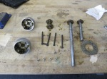
After surfing about on McMaster we found a soft rubber wheel which already had a bearing for 13.18 each. Ouch. However, what attracted us was the flat surface and the apparently hard material used to make the wheel (both of which would help us when we wanted to attach the sprockets/brakes etc.).

Then followed a bunch of stuff like brake pads and ball joints and threaded rods and bronze thrust bearings etc. and we’re left with… 54.75!

And we haven’t even got to bolts and nuts and brakes and aluminium rods (for steering). Oh dear. Regardless, the BOM is here for your viewing pleasure (whoever you are):

Description Name Vendor Unit Price Quantity Total Part ID
Motor Controller KBS36051 Kelly Controller 59.99 2 119.98 KBS36051
Motor Turnigy Aerodrive 6374-149kv HobbyKing 80.08 2 160.16 6374-149kv
Brake Pads Clarks Shimano Road Brake Pads Jenson USA 3.99 1 3.99 BR271D00
Wheels High Performance Rubber Tread Wheels with Soft Tread and General Purpose Bearings McMaster-Carr 13.18 4 52.72 2829T18
Accelerator Pedal Foot Pedal Throttle Cable (Hall Effect) TNC Scooters 12.5 1 12.5 THR-101125
Ball Joint Ball Joint Linkage Shielded, Steel, 1/4″-28 Right-Hand Thread Size McMaster-Carr 2.94 4 11.76 6058K25
Threaded Rod ASTM A193 Grade B7 Alloy Steel Threaded Rod Plain Finish 1/4″-28 Thread, 3′ Length McMaster-Carr 4.78 1 4.78 92580A107
Thrust Bearing Graphite SAE 841 Bronze Thrust Bearing for 3/8″ Shaft Diameter, 3/4″ OD, 1/8″ Thick McMaster-Carr 1.09 4 4.36 7447K3
Battery A123 Systems ALM 12V7 A123 75 1 75


Choices choices…

And so our lordcommander instructor Charles told us that a differential would be too ambitious a project in such a short timespan. Somehow or another he was extremely convincing, so we agreed to not make the most awesome electric go kart under 500 be so ambitious. So here are some of things that we’ve decided on:

  1. Four Wheels
  2. Around a 1-5 Gearing
  3. Probably going for four battery packs
  4. Two BLDC motors and two kelly controllers

Steering hasn’t been decided on yet but we get the feeling we’re gonna be able to hodgepodge it later on into something beautiful.

The reality is that our kart is now going to look very much like the chibikart except probably much bigger, because we like more leg room.

Even the braking system is probably gonna be similar (a brake pad on the outrunner) because of the added complexity of having to add a brake disc on top of a sprocket onto a wheel.

But then again imitation is the highest form of flattery =/

Differential Disassembly

We found a cheap differential and we thought we’d disassemble it, just to learn more about them so we could decide better if we wanted to construct/buy one (the one we could order was almost the exact same thing from Surplus Center).

it was an extremely simple design, but at least we learnt sort of how much material to expect, how a simple bevel differential works etc.